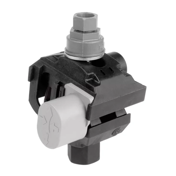
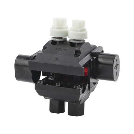
An insulation piercing connector (IPC) is an electrical component designed to create a secure and reliable connection by penetrating the insulation of a wire without the need for stripping. It ensures a seamless electrical link while preserving the insulation’s integrity. This innovation creates a reliable, insulated connection between two conductors. It works in low- and medium-voltage overhead power distribution networks, street lighting systems, and service connections. The insulation piercing connector contains sharp metallic teeth or blades inside the connector. The connector maintains full insulation and waterproofing to ensure safety and prevent corrosion. Insulation piercing connectors function in power distribution, telecommunication, and automotive systems.
The working principle of the insulation piercing clamp
Insulation piercing connector works by creating a secure, low-resistance electrical connection between two insulated conductors. During the installation, the main conductor and the branch are placed in their respective slots inside the clamp body. A wrench or socket tool helps tighten the shear head bolt. After torque, the shear head bolt snaps off to ensure uniform compression and contact pressure. The built-in gel surrounds the pierced area to provide waterproof and corrosion protection. The clamp body remains insulated to prevent exposure of live parts. This results in a stable, low-resistance connection between the main branch conductors. This maintains electrical efficiency and mechanical strength. The working principle of the connector depends on piercing through insulation with precision teeth. This establishes a direct conductive contact and seals the connection against environmental elements.
Insulation Piercing Connector
The Insulated Piercing Clamp (IPC) is a reliable connector designed for low- and medium-voltage overhead power line construction. It enables quick, safe, and permanent branching or tapping of main conductors without stripping the insulation. By incorporating sharp, corrosion-resistant teeth, the clamp pierces through conductor insulation to establish a secure electrical connection while maintaining full insulation integrity.
Key Features:
- Insulation-Piercing Technology: Allows direct connection without stripping conductor insulation.
- Waterproof Sealing: Ensures moisture resistance and long-term reliability.
- Corrosion-Resistant Materials: Stainless steel and UV-resistant polymer housing extend service life.
- Torque-Controlled Shear Head Nut: Guarantees optimal contact pressure and prevents over-tightening.
- Wide Conductor Range Compatibility: Suitable for both aluminum and copper conductors.
- High Electrical and Mechanical Strength: Provides stable performance under load and vibration.
- Tool-Free Maintenance: Once installed, requires no additional servicing.
Importance of insulation piercing connectors
Insulation piercing connectors ensure efficient, safe, and reliable network connections. Their design enables ease of installation and maintenance in modern infrastructure. IPCs reduce the need to strip the insulation from cables, allowing technicians to install them quickly and safely on live lines. Their sharp metal teeth pierce through the insulation to make contact with the conductor. Their use helps reduce the risk of electric shocks, short circuits, or accidental contact. IPCs maintain consistent electrical contact and mechanical strength over time. Their sealed, insulated design prevents moisture ingress, corrosion, and oxidation. Most of the connectors are compatible with both aluminum and copper conductors, which is crucial for mixed-material networks. The insulation piercing connector in telecommunication networks establishes reliable electrical and signal connections between cables without damaging the insulation. Their UV-resistant and waterproof design offers longevity and network stability in diverse conditions.
Key components of the insulation piercing connector
An insulation piercing connector consists of various parts working together to ensure safe, durable, and efficient electrical connections between the insulated conductors. Proper selection and understanding of the components help explain the importance of the connector in power distribution and communication systems. Here are the key components of the IPC.
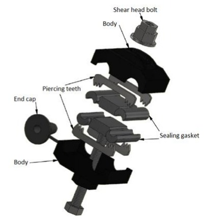
- Connector body—this is the structure that holds all the parts of the IPC together. It consists of high-strength, UV-resistant thermoplastic or glass fiber-reinforced polymer. It provides mechanical strength and electrical insulation.
- Contact teeth—these are the metallic, sharp-edged conductors embedded inside the clamp. They comprise of tinned copper, aluminum alloy, or brass for high conductivity and corrosion resistance. The teeth pierce the cable insulation during tightening to create a direct, low-resistance electrical contact with the conductor core.
- Shear head bolt—the shear head bolt ensures consistent pressure during installation. The head is designed to break off automatically when the correct torque is reached.
- Sealing compound (waterproof gel)—this is a layer of dielectric grease or sealing gel applied inside the clamp. It prevents moisture ingress, protects against corrosion, and ensures stable conductivity.
- End caps—these are rubber or plastic caps fitted on the ends of the connector. It seals off the cable entry points to prevent dust, dirt, and water from entering. It also provides strain relief for the conductors.
- Pressure plates—the pressure plates are between the bolt and the teeth to help distribute pressure across the contact area.
- Insulation end cap—these are detachable insulating end caps that cover the branch connection. It provides full insulation and waterproofing even when the branch cable is not connected.
Common types of insulated piercing clamps
Standard insulation-piercing connector
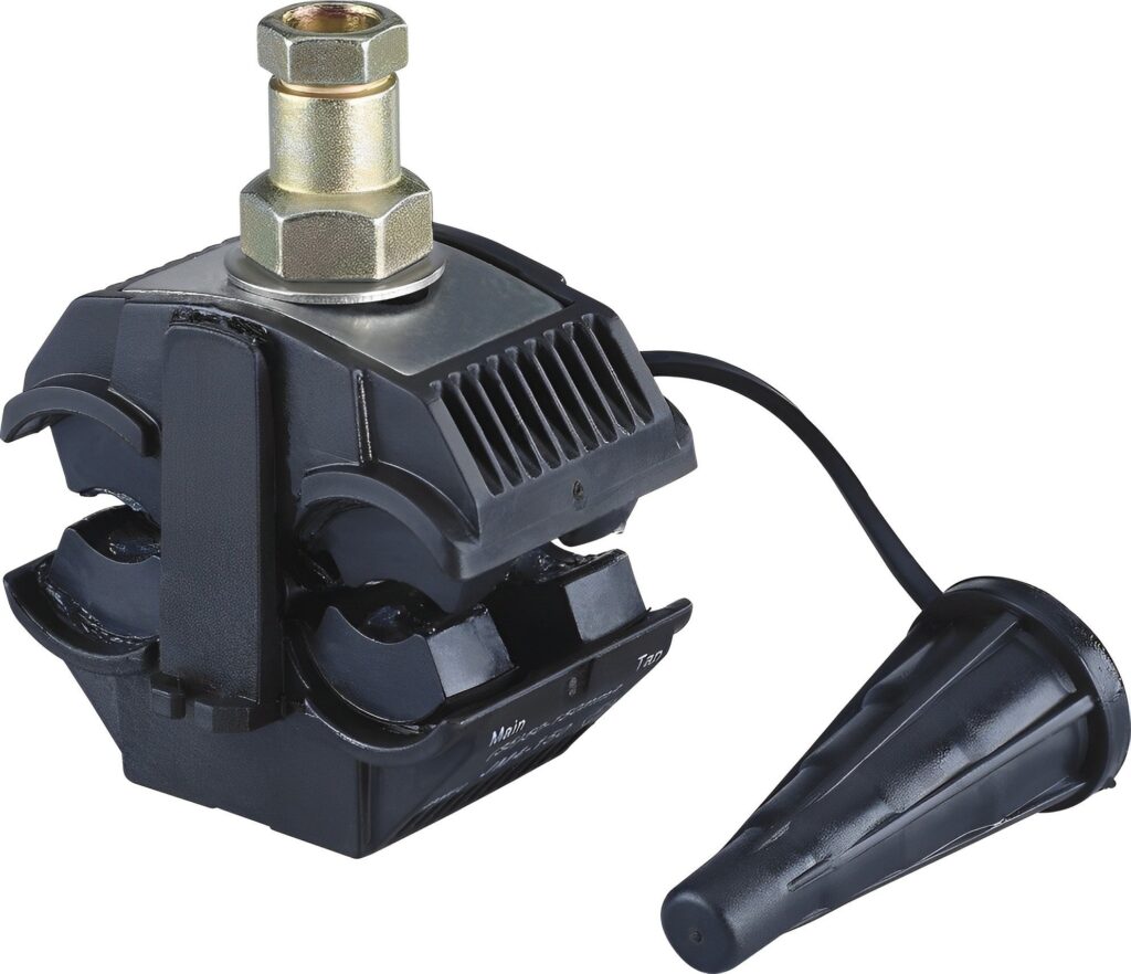
This type is mostly designed for general power distribution networks in low-voltage aerial bundled cable systems. It features one hear bolt for easy installation, connects main and branch conductors, and is filled with sealant gel to ensure waterproofing. It works in overhead distribution lines, service connections, and street lighting circuits.
Double bolt IPC
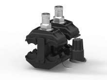
This features two shear bolts for a stronger mechanical grip and electrical reliability. It provides a greater clamping force, making it ideal for high-load connections, and offers enhanced vibration resistance. It functions in main-to-main conductor connections, medium-voltage overhead networks, and industrial installations.
Service tap insulation connector
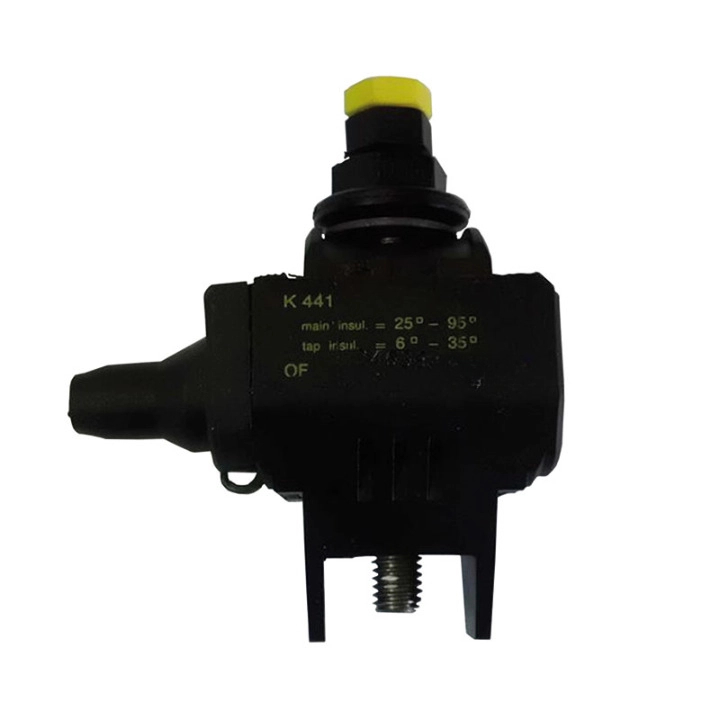
This can tap a smaller branch cable from a main distribution conductor. It allows main-to-branch connections without interrupting the power supply. It has a compact design with single-bolt operation. The insulation piercing connector functions in street lighting connections, service drops, and renewable energy systems such as solar.
Medium-voltage IPC
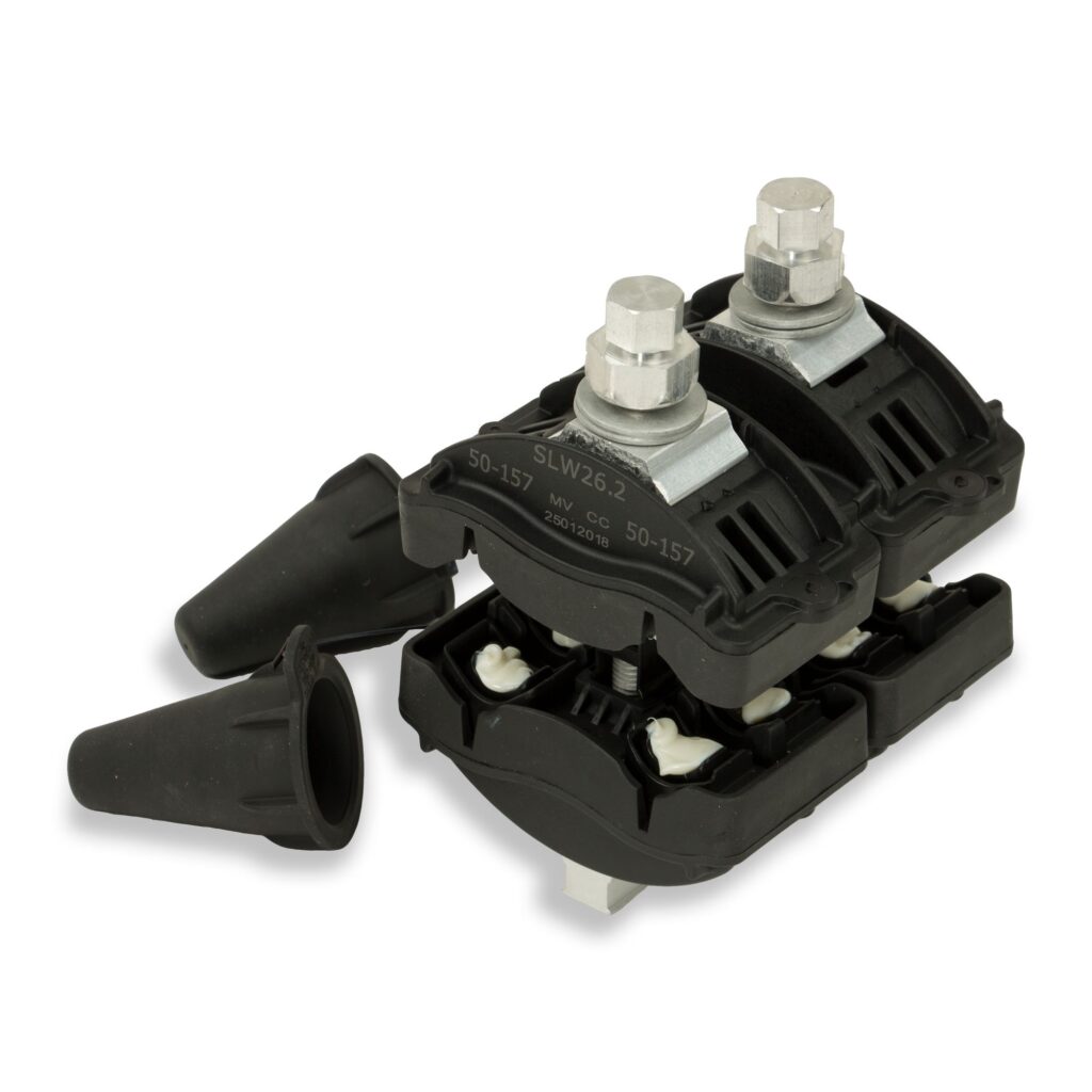
This connector is designed for medium-voltage networks with a voltage rating of up to 36 kV. It consists of reinforced polymer with enhanced dielectric strength, contains many piercing teeth for uniform contact, and is fully sealed against water, dust, and corona discharge. It works in medium-voltage power distribution networks, industrial power systems, and renewable energy grids.
Uninsulated branch connector
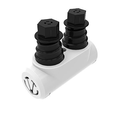
This connector provides flexibility for network expansion, has a cap that maintains insulation, and prevents corrosion. It functions in temporary installations, expansion-ready power grids, and modular distribution systems.
Technical specifications for insulation piercing connectors
The specifications of the insulation piercing connector define their mechanical strength, electrical performance, and environmental durability. They also ensure the connector meets safety standards and performs reliably in power distribution, telecommunication, and renewable energy systems. These specifications include:
- Rated voltage—this is the maximum operating voltage the IPC can handle safely. The range includes 1 kV low voltage and medium voltage up to 36 kV. This ensures that the connector can withstand electrical stress without breakdown.
- Rated current—this shows the maximum continuous current the insulation piercing connector can carry without overheating or degrading insulation. This helps prevent overheating, ensures energy efficiency, and supports load stability.
- Conductor size range—this specifies the cross-sectional area of the main and branch conductors that the IPC can accommodate. The typical range is between 16 and 150 mm² for the main conductor and 1.5 and 95 mm² for the branch conductor. This guarantees compatibility with various conductor sizes in electrical and communication networks.
- Contact material—the piercing teeth consist of high-quality metals to ensure conductivity and corrosion resistance. Common materials include tinned copper, aluminum alloy, and brass. The materials help provide low contact resistance and long-lasting electrical performance in harsh environments.
- Connector body material—the outer body provides mechanical strength and insulation. It consists of UV-resistant thermoplastic or glass-fiber-reinforced polymer.
- Bolt type and torque—insulation piercing connector uses shear head bolts designed to apply a precise amount of pressure during installation. This prevents overtightening or undertightening to ensure consistent electrical contact pressure.
- Insulation resistance—this measures the connector’s ability to resist electrical leakage through its insulating body. The insulation prevents short circuits and enhances safety during operation.
- Operating temperature range—this specifies the safe ambient temperature limits under which the connector can perform effectively. This ranges from –30°C to +120°C.
Testing the insulation piercing clamp
Testing the insulation piercing connector ensures that it performs safely, efficiently, and reliably in the electrical network. Proper testing verifies that the clamp provides secure mechanical strength, low contact resistance, excellent insulation, and waterproof protection under real operating conditions. Here are the methods, procedures, and their significance.
- Visual and physical inspection—this helps identify physical defects or manufacturing issues. It involves checking for cracks, deformation, or material defects; metallic teeth for corrosion; and ensuring the shear head bolt is intact.
- Contact resistance test—this test checks the electrical continuity and connection quality between the main and branch conductors after installation. The test involves connecting a micro-ohmmeter across the conductors joined by the insulation piercing connector, measuring the voltage drop while passing a constant current. It ensures low electrical resistance for efficient current flow and minimal power loss.
- Mechanical tightness and torque test—this verifies that the shear head bolt provides the correct tightening torque and ensures a secure and uniform connection. It involves tightening the bolt until the shear head breaks off and measuring the torque value using a calibrated torque wrench.
- Insulation resistance test—this measures the connectors’ ability to resist electrical leakage through their insulating bodies. It involves the use of a megohmmeter set at 1000 V DC and connecting one terminal to the conductor and the other to the outer body of the IPC. This verifies that the insulating material provides enough resistance against current leakage.
- Tensile strength test—this checks the IPC’s ability to withstand mechanical stress from tension, vibration, or conductor movement. It involves applying tensile force to the connected cables using a dynamometer. It helps confirm that the clamp can hold conductors firmly without slippage or mechanical failure under tension.