Power transmission infrastructure needs robust components to support and insulate the distribution system. Pole-top pins work with pin insulators to support the insulator at the top of the pole. Utility pins serve as the mounting base for insulators that hold and secure conductors on utility poles. The pole top pins ensure that pin-type insulators remain firmly in place against mechanical stress and environmental conditions. The pole top pin consists of hot-dip galvanized steel that provides tensile strength. This allows it to resist high temperatures, dust, water, and chemicals. Other common materials used include ductile iron, polymer, or composite options. The use of utility pins keeps energized conductors insulated from the grounded pole structure. The pins also allow various line designs, depending on voltage class and utility requirements.
The working principle of the pole top pins
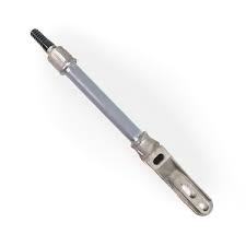
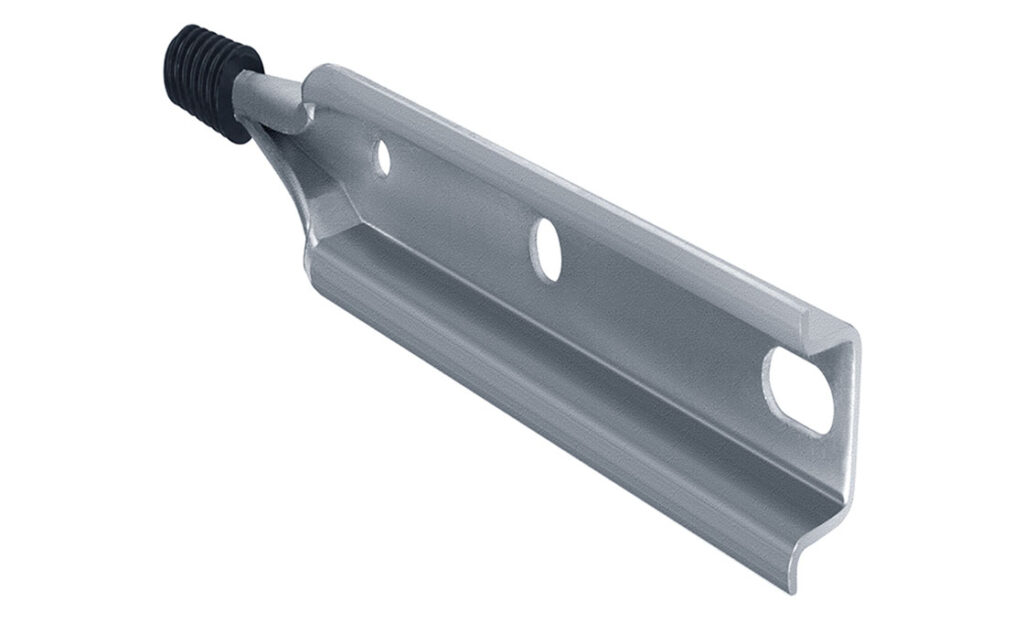
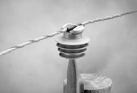
Pole top pins sit on the crossarm or directly on the top of a utility pole. It holds the pin-type insulator that supports the conductor. During installation, the pole top pin is fastened to the pole’s top or crossarm using bolts. It keeps the crossarm rigid under mechanical loads and tension. The threaded part at the top of the pin holds a pin-type insulator. The insulator prevents the conductor from making electrical contact with the grounded pole. Utility top pins support insulators carrying both the mechanical load and the electrical load through the conductor. Integration of the pole top pin and insulator ensures there is enough clearance between the live conductor and the grounded pole. This helps reduce the risk of flashovers, leakage currents, and short circuits on power lines. The utility pins work in low- to medium-voltage distribution lines and high-voltage transmission lines.
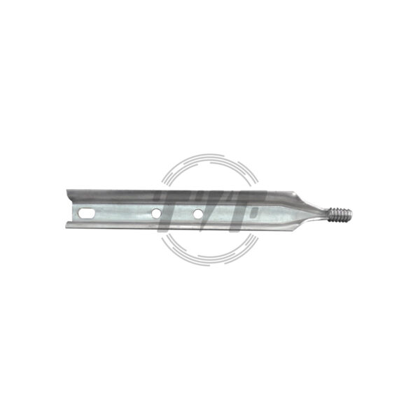
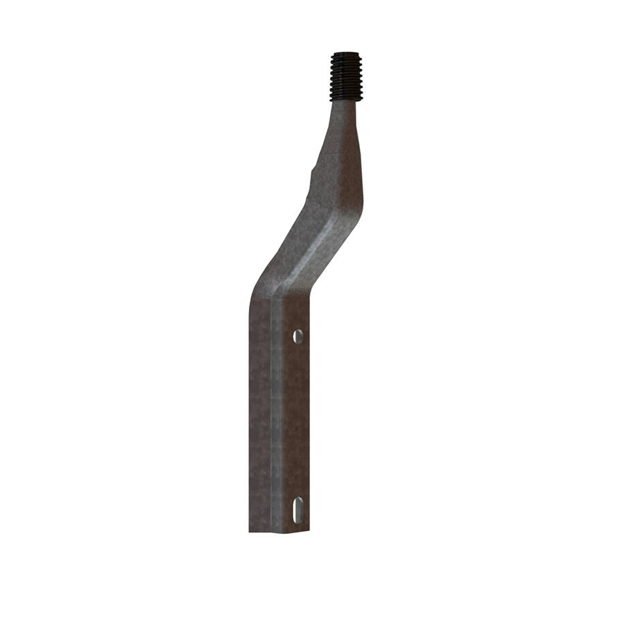
Insulator Pole Top Pin
The Pole Top Pin is a robust line hardware fitting designed for mounting pin-type insulators on distribution and sub-transmission poles. Manufactured from high-strength steel, ductile iron, or composite materials, it provides secure mechanical support and ensures reliable electrical insulation for conductors in overhead power line construction. The pin is hot-dip galvanized or polymer-coated for superior corrosion resistance, making it suitable for long-term use in diverse environmental conditions.
Key Features
- Material: Forged steel, ductile iron, or fiber-reinforced composite.
- Coating: Hot-dip galvanized (85–100 μm) for corrosion protection.
- Threading: Standard 1”–1 ⅜” UNC threads to fit pin-type insulators per IEC/ANSI standards.
- Mechanical Strength: High tensile and bending strength to withstand conductor loads, wind, and vibrations.
- Mounting: Compatible with wooden, steel, or concrete poles; suitable for pole-top or crossarm installations.
- Voltage Application: Designed for overhead distribution lines up to 33 kV and sub-transmission up to 66 kV.
- Durability: Resistant to weathering, UV radiation, and environmental stress for extended service life.
Significance of crossarm pins in power transmission and distribution lines
Pole top pins ensure the safe and efficient operation of overhead power systems. They provide mechanical support, electrical insulation, and system reliability. Crossarm pins provide the foundation for pin-type insulators that ensure they stay attached to the top of poles. They hold the insulators and maintain the insulation barrier between the live conductor and the grounded pole. This prevents faults like flashovers, short circuits, or current leakage to the pole structure. Pole top pins transfer mechanical stress to the pole while keeping the conductor in place. In distribution networks, crossarm pins ease the configuration to single-phase, two-phase, or three-phase line arrangements. This allows utilities to build flexible and cost-effective systems without the need for expensive hardware. Pole top pins are essential in transmission and distribution lines by providing mechanical strength, electrical safety, and cost-effective line designs. They serve in low- to medium-voltage lines, sub-transmission lines, and high-voltage transmission lines.
Key features of the pole top pins
Pole top pins are durable, mechanically strong, and electrically safe components. They enable the secure installation of insulators and conductors in overhead power lines. Here are the key features of the pole top pins.
- Robust material construction—pole top pins are from mild steel, forged steel, ductile iron, or composites. They are also hot-dip galvanized for corrosion resistance and long service life in outdoor conditions.
- Threaded design—the pins have threading at the top to hold pin-type insulators. It ensures tight locking and prevents insulator slippage under load.
- High mechanical strength—the pole top pins can withstand conductor tension, wind pressure, and environmental stresses. They provide structural stability in distribution and sub-transmission lines.
- Electrical safety—the pins work in conjunction with the insulator to maintain clear separation between live conductors and grounded pole structures. This is crucial to reduce the risk of flashovers, arcing, and current leakage.
- Mounting and versatile applications—pole top pins can fit wooden, steel, or concrete poles. This makes it easy to mount directly on the pole or crossarm using bolts and nuts. They are ideal for single-phase, two-phase, or three-phase line configurations.
- Low maintenance needs—the pins need minimal inspection and servicing, which contributes to reduced operational costs for utilities.
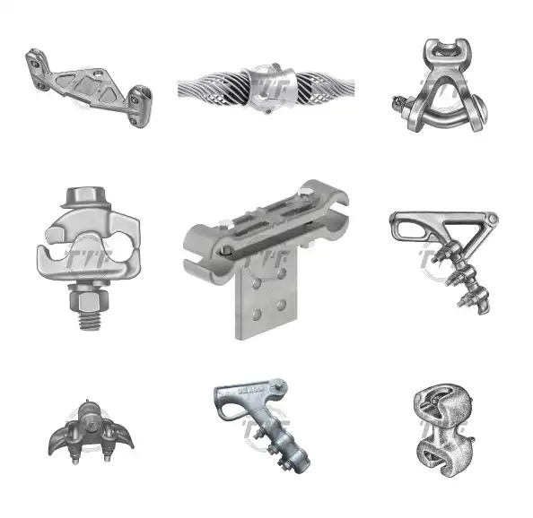
Types of utility top pins
Steel pole top pins
These pins are strong, durable, and capable of handling heavy mechanical loads. They are ideal for distribution and sub-transmission lines. Its forged steel, mild steel, or hot-dip galvanization is crucial for corrosion resistance.
Ductile iron crossarm pins
These consist of ductile cast iron, which combines strength and flexibility. It provides excellent mechanical strength and impact resistance. This makes it ideal for areas prone to strong winds or mechanical stress.
Composite or polymer pole top pins
These pins are from fiber-reinforced polymer or advanced composites. They are lightweight, non-conductive, and resistant to corrosion. This provides extra insulation and function in modern networks.
Crossarm-mounted steel pins
These are pins mounted directly on wooden or steel crossarms. These are common where many conductors are supported in three-phase line configurations.
Threaded and non-threaded pins

Threaded pins hold the insulator tightly in place, while non-threaded pins serve where the insulator is secured by clamps instead of threading.
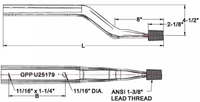
Technical specifications of the power pole pins
The specifications for the pole top pin cover the materials, dimensions, strength, coatings, and standards. The pole top pins are specified by material, size, threading, strength, coating, and compliance with standards. This ensures the durability and compatibility with insulators in overhead line networks. The specifications include:
- Material – pole top pins are from forged steel, ductile iron, and composite materials. These provide durability, high tensile strength, non-conductivity, and corrosion resistance.
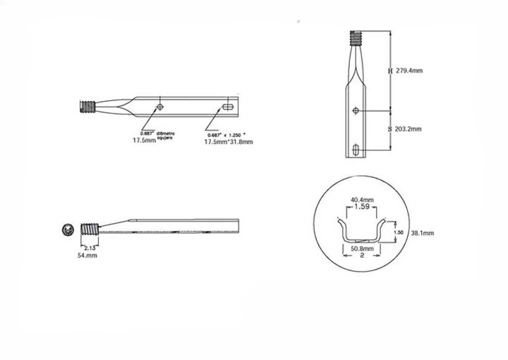
- Dimensions—the shank diameter is usually 20-25 mm, depending on pole and insulator type. It also has a threaded length for insulator fit and a length ranging from 200 mm to 450 mm.
- Threading—threads prevent loosening under vibration or load stress. The ANSI/IEC standard threading is crucial for compatibility with pin-type insulators.
- Mechanical strength—the pole pins withstand conductor tension, wind loads, and ice and snow loading. The least tensile strength ranges from 350 to 600 MPa.
- Coating and finish—the pins are hot-dip galvanized for corrosion resistance. Some of the pins feature UV-resistant polymer coatings.
- Insulator compatibility—the utility pins are designed to fit pin-type insulators rated up to 33 kV or 66 kV. The thread size and profile must match the insulator base.
- Mounting options—the pins bolt onto wooden or steel crossarms, fixed directly on the pole top, and the mounting hole ranges from 16 to 20 mm in diameter for secure bolting.
Applications of pole top pins
Pole top pins work in conjunction with pin-type insulators to support conductors in overhead lines. They provide mechanical support and electrical insulation for grid reliability. Pole top pins in overhead power line infrastructure ensure the safe and efficient support of conductors. Their main functions in overhead power lines are as detailed below.
- Distribution networks—pole top pins hold pin-type insulators that support phase conductors. They are ideal for 11 kV, 22 kV, and 33 kV feeders supplying residential and commercial loads.
- Sub-transmission lines—the pins work in secondary transmission where pin-type insulators are used. They provide cost-effective solutions compared to suspension-type insulators. They are common in regional interconnections between substations and distribution networks.
- Rural electrification projects—steel pins allow mounting of single-phase or three-phase insulators on poles without heavy towers. They are ideal for remote areas with low-to-medium load demand.
- Pole-top and crossarm configurations—the pins work in pole-top configuration for single-circuit lines. They mount on crossarms in three-phase networks to maintain conductor spacing and clearance.
- Emergency power lines—utility pins are ideal for quick installation and distribution lines during emergencies or repairs. Their simple design makes them easy to install and replace in the field.
- Support for communication lines—steel top pins are adapted to support telecommunication or signaling wires on shared utility poles.
- Diverse environments—selecting the right material for various environments is crucial to maintain their durability. For instance, coastal and industrial zones need composite or galvanized pole top pins that resist corrosion. High wind areas need ductile iron pins that provide extra strength against mechanical stress.
Installation process of the pole top pins
The installation of pole top pins should ensure mechanical stability, electrical safety, and proper alignment of the conductors. Correct installation helps reduce the risk of faults or outages in power networks. The installation process includes the selection of the correct pole top pin on line voltage, positioning on the crossarm or pole, drilling mounting holes in the pole, and inserting the pin through the hole and securing it with bolts and nuts. Mounting the insulator involves screwing the pin-type insulator onto the threaded part of the pole top pin. The insulator is then secured with a tie wire, armor rods, or conductor ties, depending on the line design. It ensures proper tension and alignment to prevent sagging.
Proper use of the crossarm pins in power transmission and distribution networks
It is crucial to follow best practices to ensure long-lasting, safe, and efficient overhead power line installations. These practices include selection, installation, maintenance, and safety. It includes choosing the current material based on the environment, conductor tying practices, correct installation, corrosion protection, regular inspection and maintenance, environmental adaptation, and safety protocols. Following these measures and manufacturer recommendations extends the service life of lines, improves network reliability, and reduces outages.