
Pre-twisted wire tension clamp (wire tension clamp) is a kind of tension clamp with strong pull and easy to operate. It is commonly used on bare conductors and over insulated conductors on main and branch distribution lines.The tensile strength is better than any other wire tension clamp.Therefore, they can replace the common tension clamp including bolt type clamp used on electric towers.
The structure of wire tension clamp is simple. The two legs of the pre-twisted wire are twisted to form an empty tube, the end is a pre-twisted ring. The tubes form by the legs of pre-twisted wire wind around the wire, producing strong tensile strength. The pre-twisted ring can fix it on the insulators. The unique principle and structure makes the wire tension clamp specific preference and characteristic.
Common Specifications
| Diameter (mm) | Wire Type | Clamps Length (ref.) | Clamp Weight | Color | |
| Minimum | Maximum | Steel Core Aluminum Wire | (mm) | (kg) | |
| 5.17 | 5.79 | 16/3 | 444 | 0.1 | Brown |
| 6.54 | 7.34 | 25/4 | 546 | 0.1 | Yellow |
| 7.35 | 8.26 | 35/6 | 622 | 0.2 | Red |
| 9.26 | 10.39 | 50/8 | 685 | 0.3 | Yellow |
| 10.41 | 11.68 | 70/10 | 736 | 0.6 | Blue |
| 13.12 | 14.66 | 95/15 | 876 | 0.8 | Red |
| 95/20 | |||||
| 120/7 | |||||
| 14.67 | 16.59 | 120/20 | 889 | 1.1 | Black |
| 120/25 | |||||
| 150/8 | |||||
| 16.6 | 18.77 | 150/20 | 1016 | 1.7 | Green |
| 150/25 | |||||
| 150/35 | |||||
| 185/10 | |||||
| 18.78 | 21.26 | 185/25 | 1155 | 2.3 | Orange |
| 185/30 | |||||
| 210/10 | |||||
| 185/45 | |||||
| 210/25 | |||||
| 210/35 | |||||
| 210/50 | |||||
| 21.27 | 24.05 | 240/30 | 1270 | 3 | Blue |
| 240/40 | |||||
| 300/15 | |||||
| 300/20 | |||||
| 24.06 | 27.2 | 300/25 | 1442 | 1.7 | Brown |
| 300/40 | |||||
| 300/50 | |||||
Formed Wire Producing
Choosing Tools
- Adjustable wrench
- Flat pliers
- Steel tape
- Makers
- Wire pliers
Raw Material Preparing
Cable LGJ-185(3 m)
Tension clamp NLD-4
Aluminum wrap (10 mm width)
Marking
Use marker to draw a clear location (given by examiner) for clamp installation on the wire
Wrap Aluminum Wires
Wrap the aluminum wrap closely. Wrapping direction should be the same as the outer layer of aluminum stands, which is from middle line to the sides. The gap of the aluminum wrap should not bigger than 1 mm.
Install Tension Clamp
The direction and the location of installation should be correct.
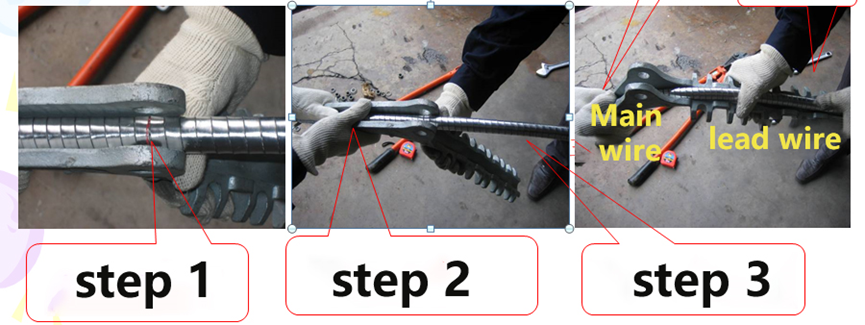
Step 1: The line need to be drawn on the middle of the clamp.
Step 2: Find the right position, one holds the wire and clamp tightly.
Step 3: Another one holds the lead and slowly presses down.
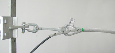
Install U-bolt
U-bolt should be installed sequentially from the suspension side to the outlet side.
The first u-bolt on the suspension side should be moderately tight. Flattened the spring washer, which is the throat of the wire clip. It act as a shock absorber.
The force should not be too large when installing the second u-bolt with moderate tight. The surface of the wire can be pressed into the recess.
When finishing the installtion of the third u-bolt, expose the end of the aluminum-covered tape 10mm from the wire clip, wrap it three times and press it into the wire clip.
Installation Requirement
The pressure block is flat and in a straight line.
The length of the wire on both sides of the U-bolt is the same.
All spring washers must be flat and complete with pins.
The water proof surface of the nut should face up (chamfered surface)
Other Requirement
Dress correctly (uniform、shoes、helmet、gloves)
Clean up the working site (in line with the requirements of civilized production)
The installation direcion and position should be correct.
How to Install

step 1. Install the U-shape ring on extension rod.
step 2. Plug one end of the tension clamp into the U-shaped ring.
step 3. Paralleled two ends of the wire tension clamp to the optical cable, then mark with tape on the optical cable according to the color code on the wire tension clamp.Finally, install the wire tension clamp.
step 4. Place one sub-bundle of the pre-twisted wire parallel to the cable and align its end color mark with the previous reference mark.
step 5. Start winding the pre-twisted wire from the center color code of the sub-bundle, but keep the ends of the pre-twisted wire loose.
step 6. Repeat the previous step. Make sure that all pre-twisted wires are installed smoothly and naturally without overlapping.
step 7. After finishing all the installation, winding the end of the pre-twisted wire by hand. Do not use any tools in case damaging or scratching the fiber optical cable.
Step 8. Align the wire tension clamp with the color code at the end of the pre-twisted wire.
step 9. Wind one end of the pre-twisted wire for one to two turns to the wire tension clamp.
step 10. Wind another end as the same beginning with distinguish the color code.
step 11. Wind both ends of the tension pre-twisted wire simultaneously until complete. During this process, make sure that the ends are bent radially outwards along the cable to avoid squeezing the pre-twisted wires. Do not wrap one end at a time!
step 12. For the convenience of installation, it is also possible to divide the part of about 20 cm from the end of the pre-twisted wire into several smaller sub-bundles. Do not use any tools to avoid damaging or scratching the fiber optic cable. Make sure that all pre-twisted wires are wound evenly.
step 13. Fix the U-shaped ring on the immobility clamp of the electric tower. Finish the installation of wire tension clamp.
Note:
- Tension wire clamp should work with ADSS or OPGW according to the optical cable.
- The outer diameter and the maximum working tension (or span) of the optical cable should in line with the specific wire tension clamp.
- The specific configuration of the tension clamp: terminal pole tower – 1 set/pole tower, tension/corner/continuous pole tower – 2 sets/pole tower.
- Trained professionals use only.
- Keep safe with yourself, the hardware and the optical cable during operation.