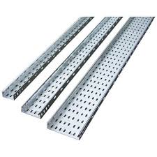
Cable racks are used for laying all-plastic cables. Cable rack has large volume, beautiful appearance, high reliability and convenient construction.
The Classification of Cable Rack
Cascade Cable Rack

The advantage of cascade cable rack is light, cheap, easy installation, good heat dissipation and nice ventilation performance. It can be used on laying the cable of 35kV with larger diameter, especially for laying high and low voltage power cables.
If classified by width, it includes 200mm, 300mm, 400mm, 500mm, 600mm and 800mm.
If classified by height, it includes 60mm, 100mm and 150mm. we do not commonly use 150mm in height, because the limitation of cable layer.
If classified by length, it includes 2m, 4m and 6m,but we always use 2m for line construction.
Tray Cable Racks

The tray cable rack is suitable for laying the cable with small diameter.They are used on controlling and laying signal cable. It also divided into 2 types which are with holes or without holes. The holes are for heat dissipation.
Through Cable Tray

The fully enclosed cable rack stamps and folds by cold-rolled steel plate with cover. The cover prevents dusts, fire, smoke and mechanical damage. It also can against interfere the signal of wires and cables used for telecommunication and computer.
Assembled Cable Tray

The structure is simple and the installation steps are convenient. You may use 100mm, 150mm and 200mm width cable rack to make your own one. You can install it without bending, tee and other accessories in any circumstances, such as arbitrary turn, widen, branch,lead up and lead down.
Large Span Cable Rack

The large span cable rack has better strengthen and better stability with bilateral or double ladder structure.
Fireproof Cable Rack
It is suitable for laying the computer cable, communication cable, lighting cable, other high sensitive controlling cable and signal cable. With shielding and anti-interference performance, the fireproof cable not only lay cables and wires, but also can install sockets, fuses, small low voltage circuit and hoisting lamps.
Components of Cable Rack
Body
Consists of straight, bend, horizontal tee, horizontal cross, vertical concave bend and vertical convex bend.
Support
It is used to support the main part of the cable rack and cables.
It composed of column, column base and support arm. They have different types, including suspended type, vertical type, side wall type, single type, double pass and multi-layer.
Column
Used to support the main part of cable rack and set the gaps.
They are 5 types of the columns. L-beam column is suitable for places with many cables, heavy loads and large spans. T-beam column is used for unilateral hoisting with light load. Channel steel column is used for leading up, leading down and hoisting. Angle steel column is light loaded and unilateral hoisting. Special shaped is unilateral hoisting. All these column is used with fixed support arm column arm.
Column Base
It is for floor fixing or hanging fixed column. It work with corresponding column.
Support Arm
It is a cross arm for installing the cable rack. Different specifications in width should be matched with the width of the cable rack.
Accessories
They serve as a set by the factory, which includes height adjusting sheet, width adjusting sheet, direct sheet, bending sheet and angle adjusting sheet. They will not be counted.
Separator
It is used on the same level of the cable rack for separating power and control cables.
Shield
It is used in places where is easy to accumulate, racks with top shielding and outdoors. The specifications should be matched with the cable rack.

Size Choose and Calculate
Power Cable
Width: B=n1(d1+k1)+ n2(d2+k2)+ n3(d3+k3)……
d1、d2、d3…… diameter of the cable
n1、n2、n3…… ammount of the cables in line with the diameter
k1、k2、k3…… gap of the(d1/4)
Levels =B/(width of the cable rack)
Control Cable
Total cross sectional area: S0=n1π(d1/2)2+ n2π(d2/2)2+……
Cross sectional area of the brackets: S=S0/40% d=S/h= S0/40%h
Levels equals to S/(600X100)
Installation Requirement
- When installing the large span cable rack indoors, the outward slope of the rack should not be less than 1/100
- When the cable rack across with the electrical equipment, the clear distance should not be less than 0.5m.
- When laying two sets of cable rack at the same level, the clear distance should not be less than 0.6m.
- When drawing the route of the cable rack on the parallel plot, you should marked the starter, ending, bending, branch and lifting point of the coordinate or position the scale and height. All these operations can make the calculation more accurate when drafting the axonometric.
Straight line: mark full length, level of cable rack,height type and standard.
Bending and branch: mark the type and standard of the bending plate.
Lifting point: mark the change of height by some large scale drawings or section drawings.


- Mark the orientation and the method of cable drop point.
- The cable rack should be 2.2m higher than the ground. The gap between the top and other obstacle should be no less than 0.3m. The width of the cable rack should not less tham 0.1m. The filling rate of the cross section in the cable rack should not exceed 50%.
- When laying the cable straightly in the rack, they should be fixed on the brackets at the upper end of the cable and every distance of 1.5m. When laying horizontally, the cable should be fixed at starter, in the end and every bending point with every distance of 3m to 5m.
- When laying on the ceiling, the open side of the slot cover should keep a straight clearance of 80mm, the use rate of the trunking section should not exceed 50%.
- The cables routed in the trunking should not be interspersed as much as possible. The cable should not overflow the wire way. The corner should be tied and fixed when the cable enter and exits the slot. The cables laid in the straight groove should be fixed on the cable bracket every 1.5 meters.
- When laying the cable in the straight rack or trunking, you should tie the cables together. The tie distance should not larger than 1.5m with even span and moderately tight.
- When laying horizontally, the support distance is 1.5m to 3m. When laying straightly, the distance fixed on the building should not be less than 2m.
- You should use steel structure or non-flammable material for the fireproof part.


