Fuse is an electrical equipment. It disconnects the circuit when the current exceeds value. When the current exceeds the rated value, the fuse can melt the melt by its heat generation, finally cut out the circuit. This the the operation principle of the fuse, or current protect. The now widely used in high and low distribution system, controlling system and in electrical devices. As a circuit protector, it is also the commonly used among others.
Functions
High voltage fuse cutout will cutout the circuit when go through the short circuit or overload current for protecting the electrical equipment. They are widely used on 3 to 35 kV small scale equipment for protecting lines working as a transformer, electric motor and voltage transformer.
Classifications
The high voltage dropout fuse can be classified as three kinds.

Examples
High Voltage Indoor Dropout Fuse
RN1
Series Indoor Limited Flow High Voltage Fuse with Filling
RN2
It is a typical cutout fuse for protecting short circuit used on voltage transformer circuit.
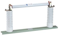
High Voltage Outdoor Dropout Fuse
RW4-10 Outdoor Dropout Fuse

RXW-35 Outdoor Limited Flow Fuse
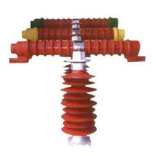
High Voltage Capacitor
Function
It is the one of the reactive power of the electrical system. It is used for improving the power factor of the power grid.
Operation and Maintenance
The general requirement of high voltage capacitor in operation:
- The brand need to be marked, including basic specifications,
- There’s no flammable and explosive hazards, and no violent shocks and vibrations around the capacitor,
- Before assembly and commissioning, we need to check the discharge circuit, protection circuit and ventilation system after all tests are qualified and inspected according to general inspection items. We should number the frame type capacitor and attach a 45℃~50℃ test wax sheet to the upper third. We need to close shock three times under the rated voltage with 5 minutes intervals. You should discharge the residual voltage before the next closing carried out.
- The maximum indoor operation temperature is 40℃, while the maximum temperature of the cover is 50℃.
- The rated voltage is about 5% in long term operation. The multiple of over-voltage and operation duration are as follow. We need try our best to avoid operation under the rated voltage.
| Multiple of Voltage(Ug/Un) | Duration | Notes |
| 1.05 | Continuously | |
| 1.10 | 8h/24h | |
| 1.15 | 30min/24h | adjustment and fluctuation of system voltage |
| 1.20 | 5 min | voltage rise at light load |
| 1.30 | 1min |
- The grounding of the cover and the frame should be reliable and the external paint should be completed.
- The capacitor set allows long term operation at 1.3 times rated current.
Precautions in Operation
- When the electric capacitor is disabled, you need to open the breaker first, then open the isolation switch on the capacitor side.
- If you fail in the first closing, do the second time 5 minutes after the first time. It is the same with the accident.
- When the whole station is out of power and the bus system is out of power, the circuit breaker of the power capacitor bank should be opened first, and then the outgoing circuit breaker of each feeder should be opened. When the power supply of the whole station is restored, the outgoing circuit breakers of each feeder should be closed first, and then the power capacitor bank circuit breaker.
- When the whole substation is powered off or the bus connected with capacitors loses voltage, the capacitor circuit breaker on the bus should be opened first, and then the circuit breaker should be opened; the capacitor should be finally put in according to the bus voltage and system reactive power compensation after the power is turned on.
Accident and Failure Handing Plan
Common Breakdown
- Deformation and bulging of the cover
- Serious oil leakage
- High temperature or abnormal sound inside.
- Booming or on fire
- Single fuse blown
- Casing flash over or severe discharge
- Contacts are severely overheated or melt
Malfunction and Solutions
Deformation and bulging of the cover
Cause: Partial discharge occurs in the medium, which decomposes the medium and releases gas. Break down some components or the cover, causing the medium to evolve gas.
Solution: Exit the operation immediately.
Oil leakage
Cause: hold up the porcelain sleeve when transportation, causing the flange welded with cracks. The screw is too tight when wiring, and welded and damaged the porcelain sleeve. The production fault. Abrupt changes in temperature. Paint peeling off rusting the cover.
Solution: Repair welding using lead and tin, but do not overheat, avoiding the silver layer on the porcelain sleeve falling off. Improve the wiring method, eliminate the wiring stress. Do not shake the porcelain sleeve during wiring and do not force the screw cap. Avoid sun expose and enhanced ventilation. Remove rust and touch up paint in time.
High temperature
Cause: Overheat the surrounding environment, density arrange of capacitors. Affect by higher harmonic currents. Open and close the capacitor frequently, causing over-voltage repeatedly. Aging of medium with the increasing of tgδ.
Solution: Improve the ventilation, increasing the gap of the capacitor. Install series reactor. Limit the operation over-voltage and current. Change in time when stop use.
Boom or on fire
Cause: If there is a break down in the internal generator or the case and there is no protection, the capacitor set connected in parallel with it discharges it, and it catches fire due to a large energy explosion.
Solution: Cut the power off immediately. Put out the fire by sand or dry fire extinguisher.
Single fuse blown
Cause: Over-voltage. Internal shortage of the capacitor. Cover insulated.
Solution: Control the operation voltage strictly. Measure the insulation and change it in time. Check the reason and change the fuse. Stop operation if there is a internal shortage. If the relative current imbalance approach 2.5%, you should change the capacity in time.
Stop Capacitor in Following Situation
- The capacitor booms.
- The joints overheat or the temperature wax of the capacitor melt.
- The casing rupture and flash over discharge.
- The fuel injection of the capacitor or on fire.
- The cover obviously bulging, the oil outflow or the three-phase current imbalance exceeds 5% or more or there is abnormal sound in the capacitor or reactor.
- The cover temperature over 55℃ or the room temperature over 40℃ and the cooling measures are invalid.
- The dense pressure relief valve shunt capacitor in its operation.