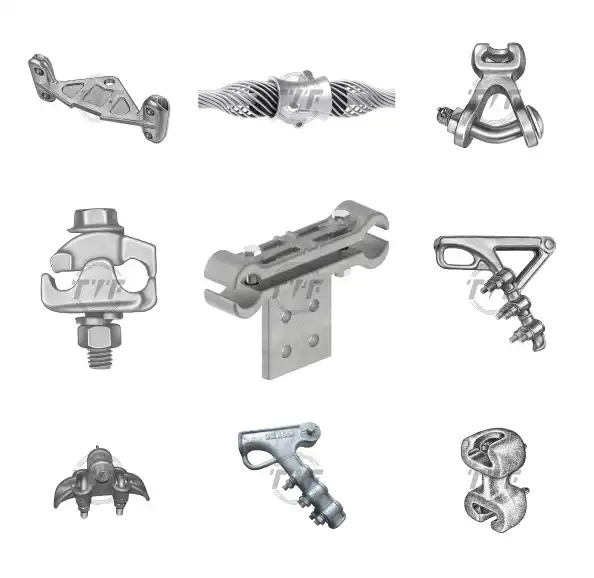
An insulator pin is a component used to hold and support insulators on utility poles and transmission lines. It serves as the mounting point for pin-type insulators that carry and electrically isolate the overhead conductors from the supporting pole. The insulator pin keeps energized conductors safe from grounded structures to prevent electrical leakage or short circuits. They are also able to withstand the mechanical load of conductors, wind pressure, and other environmental stresses. This is due to the use of steel, ductile iron, or other galvanized metals for corrosion resistance. The insulator pin features a threaded top section, a shank, different material options, and a load capacity. This allows attachment to crossarms, poles, or brackets. Insulator pins ensure mechanical stability and electrical insulation in overhead transmission and distribution networks.
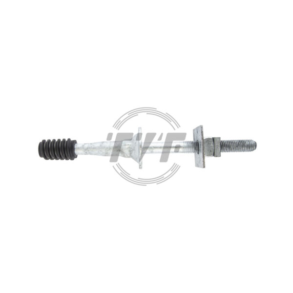
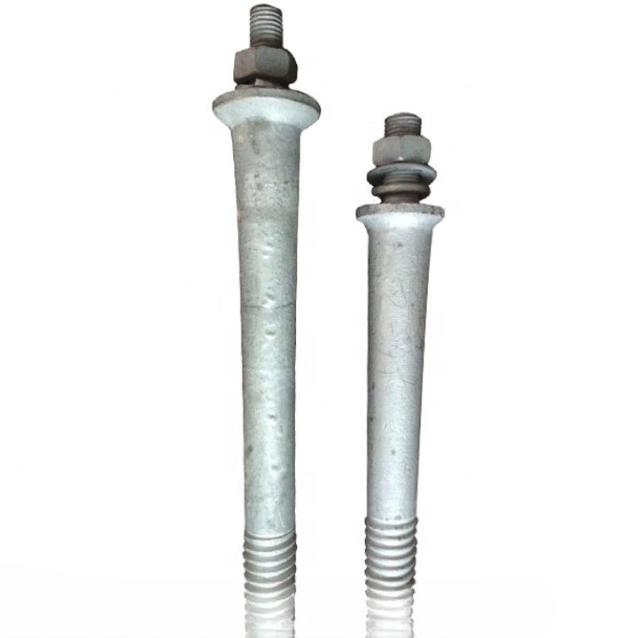
Insulator Pin with 800 lb Cantilever Load Rating
An insulator pin is a vital hardware component used in power line construction to securely mount insulators onto crossarms or poles, ensuring reliable support and electrical isolation. Designed for high mechanical strength and durability, insulator pins provide stable positioning of pin-type insulators, preventing electrical faults and enhancing transmission and distribution efficiency.
Key Features:
- Material Options: Manufactured from forged steel, ductile iron, or high-strength alloys for maximum load-bearing capacity.
- Protective Coating: Hot-dip galvanized or zinc-plated finish for superior corrosion resistance in outdoor environments.
- Threaded Design: Precision threading ensures firm attachment of pin-type insulators.
- Mechanical Strength: Engineered to withstand mechanical stresses from conductor tension and environmental forces.
- Versatile Sizes: Available in standard lengths and thread sizes to fit a wide range of insulators and crossarm configurations.
- Easy Installation: Compatible with wood, steel, and composite crossarms.
- Industry Standards: Manufactured in compliance with ANSI, IEC, or equivalent utility specifications.
Working principle of the insulator pin
Insulator pins are a crucial component in the functioning of overhead power lines. They are the mechanical and electrical link between the support structure and the pin-type insulator holding the conductor. Their design ensures that high-voltage currents are safely transmitted without compromising the stability of the network. During installation, the insulator pin is bolted onto a crossarm or pole top. Its threaded end fits into the insulator’s base to lock the insulator pin. After the attachment, the overhead conductor is tied to the top groove of the insulator. This ensures that the conductor stays in position and prevents slip. The mounted insulator prevents the high-voltage current flowing through the conductor from reaching the grounded pole. The pin’s role is to hold the insulator and allow it to perform its insulating functions. Additionally, it provides the mechanical strength to bear the loads and transfer tension to the pole structure.
Relevance of insulator fittings in overhead power lines
The insulator pin ensures both safety and reliability of the power line infrastructure. The pin provides a secure base for pin-type insulators, which hold and support live conductors. It enables the insulator to maintain electrical isolation between the energized line and the grounded structure. By supporting the insulator, the pin ensures that the current does not leak into the pole and prevents short circuits, flashovers, and potential blackouts. Their design and material enable them to withstand tension, wind, ice, and vibration forces. The insulator pin ensures the insulator remains stable under stress for transferring loads to the utility pole. Insulator pins help maintain proper alignment and spacing across the network. High-quality material pins provide durability and corrosion resistance to ensure the network remains safe and reliable. The pin guarantees that conductors are well-supported, insulated, and safely positioned to prevent power interruptions.
Key features of the insulator pin
Strength, durability, compatibility, and design define the strength of the insulator pin. Its combination of mechanical support and secure insulator anchoring makes it a crucial component in overhead power line networks. Its key features include:

- Robust construction—insulator pins are from forged steel, ductile iron, or malleable iron for high tensile strength. They may also have hot-dip galvanization for corrosion resistance to ensure long-term durability in outdoor environments.
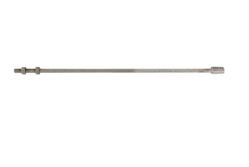
- Threaded top section—the threaded end allows it to fit into the insulator base. This provides a strong, non-slip grip to prevent loosening under vibration, wind, or conductor tension.
- Shank and base design—the shank anchors the pin to the crossarm, pole, or bracket. The base may be straight, bent, or shaped to suit different mounting requirements.
- Compatibility with pin-type insulators—insulator pins are specifically designed to work with pin insulators to ensure the correct positioning and alignment of conductors. This enables them to handle different voltage classes depending on the insulator type.
- High mechanical strength—the insulator can withstand the mechanical load of conductors and environmental stresses like wind pressure and ice loading. It prevents sagging or snapping of conductors.
- Electrical safety support—the pin ensures there are no gaps in mounting to reduce the risk of flashovers.
- Size and standards—the insulator pins are available in various sizes and specifications to match utility standards and voltage levels. They can serve in distribution lines and transmission lines at low, medium, and high voltages.
Types of insulator fittings
Straight shank pins
This is the most common type of insulator pin used in overhead distribution. It features a straight cylindrical shank inserted into crossarms or pole tops. Straight pins are suitable for light to moderate mechanical loads.
Bent shank pin
This has a bent or offset shank to provide extra stability. It serves where there is limited space or where conductors need a specific alignment on poles. They help reduce stress concentration at the mounting point.
Steel insulator pins
Steel pins are from forged or ductile steel that provides greatest mechanical strength. It serves in high-load and high-voltage applications. Their hot-dip galvanization helps withstand corrosion in outdoor and coastal environments.
Wooden insulator pin
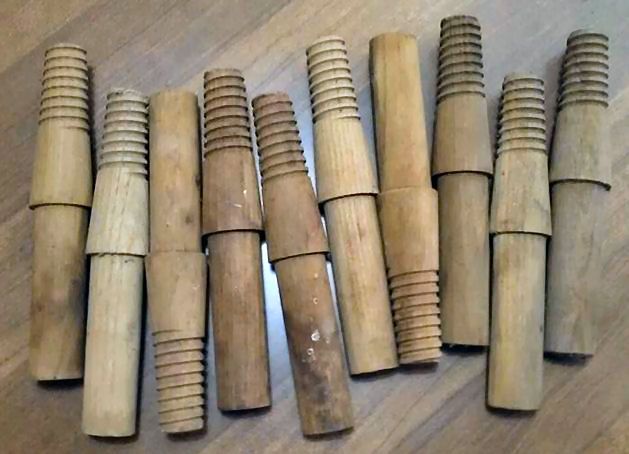
This is traditionally used on older lines made from hardwood and treated with preservatives. They provide a low-cost option but lack the strength and durability of modern metal pins.
Special heavy-duty pins
These pins are ideal for extra-large insulators in higher voltage networks. They have extra reinforcement that allows them to withstand both high mechanical tension and electrical stress.
Threaded pins

These have a threaded top end that screws into the insulator base for a tight fit. This is mostly used for porcelain pin-type insulators in lower voltage distribution lines, such as 11 kV and 33 kV.
Technical specifications for the insulator pin
The specifications of the insulator pin define its strength, durability, and compatibility with pin-type insulators. The insulator pins face high mechanical loads and electrical stresses. The specifications ensure the pin can hold the insulators, withstand environmental loads, and guarantee safe power distribution. These specifications include:
- Material—the pin is from forged steel, ductile iron, or malleable iron that ensures high tensile and compressive strength.
- Shank design—this may include a straight shank, bent shank, or offset shank. The shank is drilled or shaped for firm anchoring in crossarms.
- Threading—the threaded top of the pin matches the insulator’s base threads for secure mounting. Threads manufactured per ANSI C29 or IEC standards ensure compatibility. Some of the pins use cemented insulators instead of threads.
- Mounting—the insulator pin base is ideal for crossarms or pole tops. They mount using bolts, nuts, or direct threading into the structure.
- Dimensions—the length of the pin varies depending on the insulator type, which is commonly 6-14 inches. The shank diameter is typically 1-1.5 inches for strength and proper fit. The threaded diameter matches the insulator cavity, which is usually 1 inch.
- Mechanical strength—the insulator pins must withstand the vertical and lateral loads from conductors, wind, and ice. They can prevent bending, loosening, or breakage under stress.
- Electrical considerations—the metallic pin works with the insulator to maintain dielectric clearance between the conductor and grounded structure. Its dimensions preserve the creepage distance for the insulator.
Applications of the insulator fittings in overhead power lines
Insulator pins serve where pin-type insulators are necessary to support and insulate conductors. They secure insulator poles and crossarms to keep conductors elevated, insulated, and aligned. Insulator pins are crucial in distribution lines, rural electrification, branch lines, and temporary power installations. Here are the applications of the insulator pins in overhead power lines.

- Low and medium voltage distribution—insulator pins serve in 11 kV, 22 kV, and 33 kV distribution networks. Insulator pins secure pin-type insulators carrying conductors from pole to pole. They provide reliable insulation and support for power delivery.
- Pole-top installations—insulator pins hold insulators at the correct height and ensure conductors remain at a safe clearance above the ground.
- Transmission support—heavy-duty insulator pins serve with larger insulators and are common in sub-transmission lines that link substations to distribution networks.
- Branch lines and taps—the pins support insulators at junctions or branching points where conductors split into smaller feeder lines. They provide stable support for changes in conductor direction.
- Rural electrification projects—insulator pins are simple and reliable, which makes them ideal for low-cost distribution infrastructure.
- Temporary line setups—insulator pins mount on poles for temporary power lines during outages, repairs, or disaster recovery.
- Specialized pole configurations—the pins work with wooden and steel crossarms, depending on utility standards. Their versatility allows them to adapt to different pole designs and conductor alignments.
Following best practices when working with insulator pins
Working with insulator pins affects the safety, reliability, and service life of overhead power lines. Proper handling of the insulator pins can lead to conductor failure, insulation breakdown, or outages. When working with the pins, it is essential to select the right type and size, inspect before use, ensure proper galvanization, correctly install on crossarms, tighten insulators properly, and maintain electrical clearance. Additionally, it is crucial to regularly check for corrosion, bending, or looseness during line patrols. Utilities should de-energize the line before installation or replacement whenever possible. It is also crucial to use proper climbing gear and insulated tools, and adhere to utility safety standards. Following these practices ensures a long service life of pins, stable conductor support, and uninterrupted power transmission.