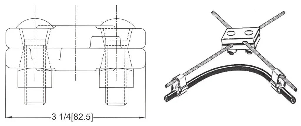
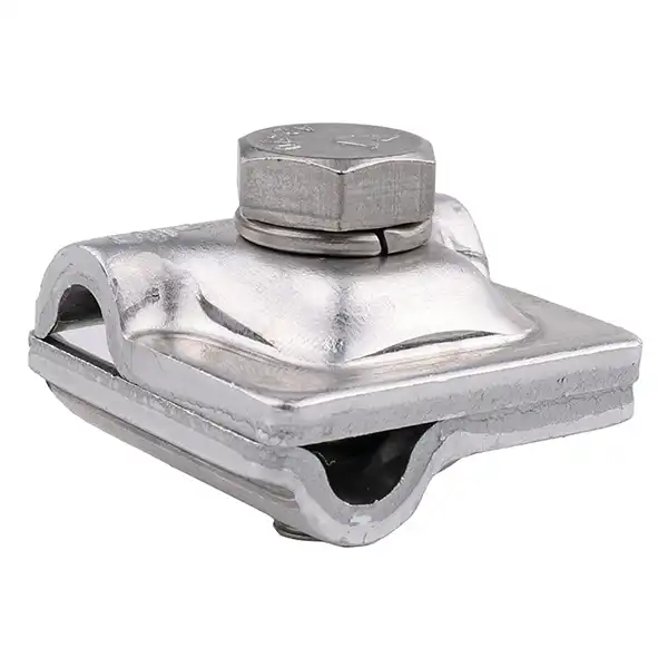
A crossover clamp is a type of power line hardware used to connect two conductors or cables that cross each other at a crossing point. They help to ensure a proper alignment and electrical continuity. It maintains the separation and positioning of the crossing conductors and prevents contact or interference between them.
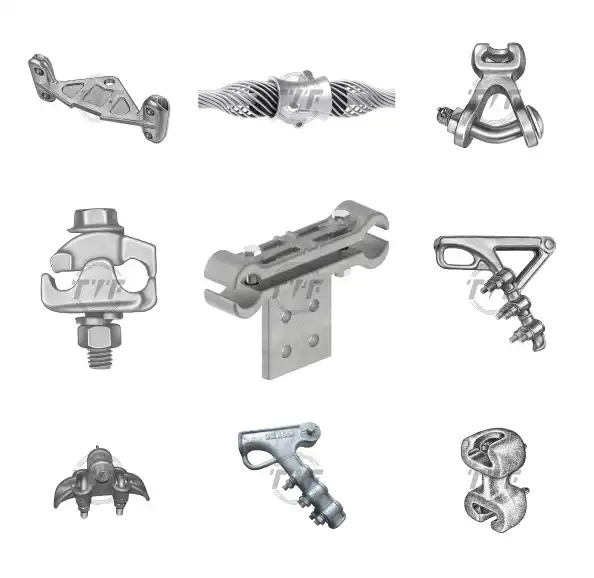
TTF is a manufacturer of crossover clamps that prevent electrical circuits, short circuits and damages to the conductors. They have two halves that connect together using bolts or other fastening techniques. Each of the half has grooves that accommodate the individual conductors. The design of the crossover clamps varies depending on the size and type of conductors, voltage level and environmental conditions. Crossover clamps are from materials with high mechanical strength, corrosion resistance and electrical conductivity.
Common technical specifications
| Specification | Value |
|---|---|
| Material | Steel / Aluminum |
| Finish | Galvanized |
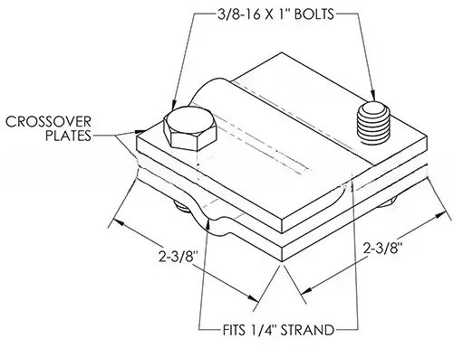
| Size | 1-1/2 to 2-1/2 inches in diameter or custom made |
| Weight | Vary |
| Bolts | Two hex bolts |
| Applications | Transmission lines, communication lines |
| Features | Does not exert excess clamping pressure, suitable for different sizes of strands, resistant to weather, easy and safe to install |
Reliable crossover clamp matters
On March 1, 2017, a power outage occurred in Hodgenville, Kentucky. The outage affected over 1,000 homes and businesses. The cause of the outage was a power line crossover clamp that had failed.
The crossover clamp was manufactured by an OEM factory in southern China. The clamp had a manufacturing defect that caused it to overheat and melt. The melting of the clamp caused the power outage.
The U.S. supplier was held liable for the damages caused by the power outage. They had to pay the town for the damage to the economy, and they also had to pay for the hotel rooms and other expenses that the residents had incurred.
The supplier has since implemented a new quality control program to prevent future failures. They are also inspecting their power line crossover clamps more frequently.
This story illustrates the importance of quality control in the manufacturing of critical equipment. A small defect in a power line crossover clamp can have a big impact on people’s lives. It is important for manufacturers to take steps to ensure the quality of their products, and to be held accountable for any defects that do occur.
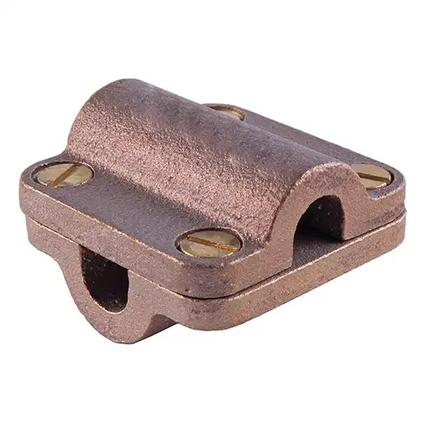
Components of the crossover clamp
Features of the crossover clamps depend on the manufacturer, application and specific requirements of the power line system. The general features of the crossover clamps are as discussed below.
Clamp body
This is the main component of the crossover clamp that is usually metallic. It holds and secures the crossing conductors in place. The body may have grooves or channels that accommodate the individual conductors
Fastening mechanism
The crossover clamps have a fastening mechanism to secure the clamp body and provide tight and secure connection. The fastening mechanisms may involve the use of bolts, nuts, screws and washers. This allows the easy installation and removal of the clamp.
Conductor grooves
The clamp has conductor grooves that accommodate the individual conductors that cross each other. These grooves ensure proper alignment and separation of the conductors and prevent contact.
Insulating inserts
These are optional inserts used within the clamp to provide mechanical insulation between the crossing conductors. These inserts prevent electrical faults and ensure proper electrical isolation between the conductors.
Corrosion protection
Corrosion protection may be in form of coatings or treatments to provide corrosion resistance. They help to protect the clamp from environmental elements such as moisture humidity and ensure its durability.
Types of crossover clamp
There are various types of crossover clamps used on the transmission lines. when selecting the clamps, it is essential to consider various factors like conductor type, voltage level, environmental conditions and specific project requirements. The following are the types of crossover clamps used on the transmission lines.
Preformed crossover clamp
These are designed to provide custom fit for specific conductor configurations and diameters. They are easy to install and offer high mechanical strength and electrical conductivity. Preformed crossover clamps are from materials such as aluminum or steel.
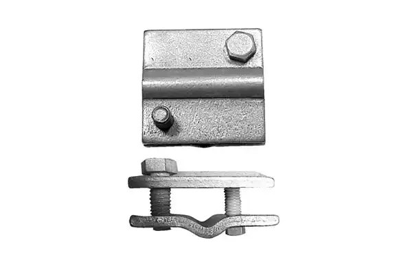
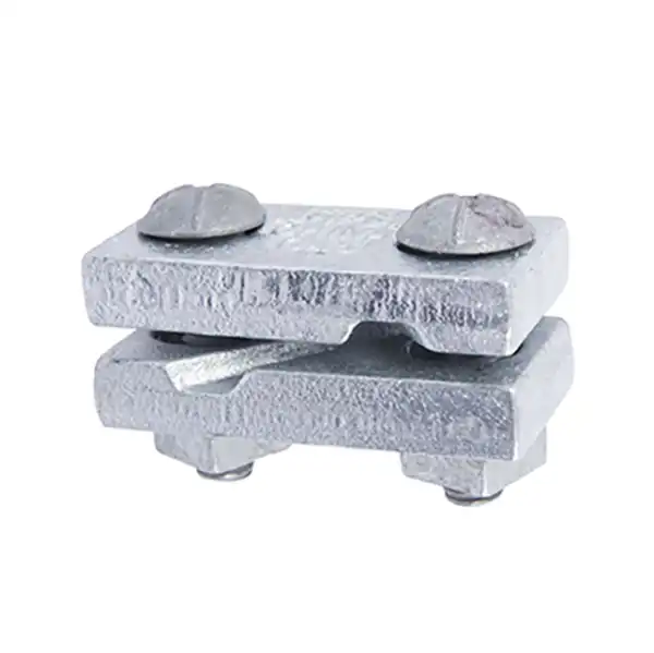
Bolted crossover clamp
Bolted crossover clamps have two halves of the clamp secured together using bolts. They provide a sturdy and reliable connection which ensures proper alignment and electrical continuity at the crossing point.
Insulated crossover clamp
Insulated crossover clamps incorporate insulating materials to provide electrical insulation between the crossing conductors. They help prevent electrical faults and ensure proper electrical isolation at the crossing point.
Wedge-type crossover
These clamps utilize a wedge or tapered design to secure the conductors in place. The wedges exert pressure on the conductors and holding them securely and maintaining their alignment. They are often used on the high-voltage transmission lines.
Tension crossover clamp
Tension clamps work in applications where there is a significant tension on the crossing conductors. They add additional support and anchorage to ensure stability and proper alignment of the conductor at the crossing point.
Automatic crossover clamp
These are also known as self-adjusting or self-tightening clamps. They are designed to automatically adjust to the size and shape of the conductors at the crossing point. Automatic clamps use springs to provide a constant pressure which ensures a secure and reliable connection.
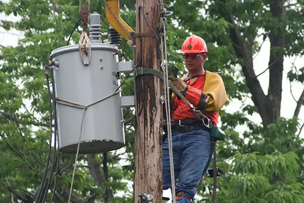
Installation of crossover clamp
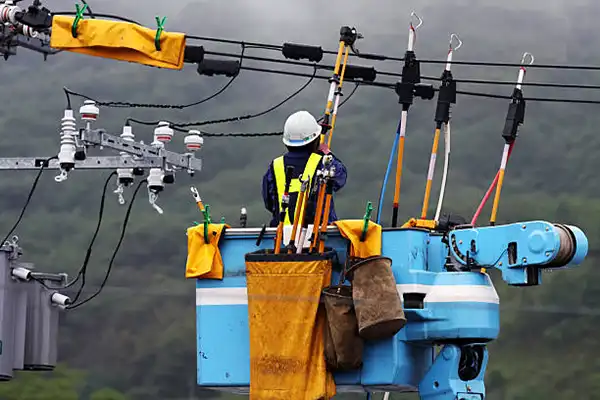
Installation of the crossover clamps depends on the design, requirement and the manufacturers instruction. Installation should also follow the instructions by a trained personnel or professionals before power line installation. The following is a step-by-step installation process of the crossover clamps.
- Prepare the work area
This involves ensuring the work area is safe and accessible. This also includes wearing personal protective equipment and ensuring the power is de-energized if required. - Identify the crossing point
Locate the point where the conductors cross each other where the crossover will be installed. This will maintain proper alignment and electrical continuity. - Clean and inspect the conductors
Clean the surface of the conductors at the crossing points to remove any dirt, grease or oxidation. You should also inspect the conductors for any damage or irregularities tat may affect the installation or performance of the crossover clamp. - Prepare the clamp
This involves ensuring the clamp is in good conditions and appropriate for the conductor size, type and voltage level. You should also check for any specific installation instructions from the manufacturer. - Position the crossover clamp
Position the crossover clamp over the crossing conductors and align the grooves with the conductors. Also ensure the clamp is centered and properly seated on the conductors. - Secure the crossover clamp
This involves the use of the appropriate fastening mechanisms to secure the two halves of the clamp together. - Check alignment and secureness
Verify the crossover clamp has securely held the conductors in place. This also maintains proper alignment and separation. Ensure there is no contact or interferences between the conductors. - Testing and inspection
Inspect the installed crossover clamp to ensure there are no defects, loose connections or signs of damage. These tests and inspections ensure proper electrical continuity and systems integrity.
Applications of crossover clamp
Crossover clamps maintain the integrity, safety and performance of the power line systems. They also ensure the conductor alignment, electrical continuity, mechanical support and corrosion protection. The following are the applications of the crossover clamps:
- Crossing conductor alignment to ensure the conductors do not come into contact with each other.
- Electrical continuity to allow the flow of electricity between the conductors without interruption.
- Mechanical support to support the crossing conductors and help maintain their position and stability.
- Load distribution through the proper aligning of the crossing conductors.
- Corrosion protection from corrosion resistance materials.
- High voltage applications for safe and efficient operation of the power systems.
- Tower attachment points on transmission towers.
Choosing the best crossover clamp
Choosing the best crossover clamp depends on the manufacturer and specific recommendations. Choosing the crossover clamps should be based on a number of factors to be considered. Here are the considerations to make the decision.
- Conductor type and size
- Voltage level
- Environmental conditions
- Manufacturer reputation
- Compliance with standards
- Installation and maintenance
- Performance and durability
- Compatibility with system components
FAQs
Crossover clamps are types of hardware used on the power lines to connect two conductors or cables.
Bolted crossover clamps
Automatic crossover clamps
Wedge-type crossover clamps
Tension crossover clamps
Insulated crossover clamps
Preformed crossover clamps
Crossover clamps applications on the power lines include crossing conductor alignment, electrical continuity, mechanical support, load distribution, corrosion protection and high voltage applications.
Easy installation and maintenance
Flexibility and compatibility
Enhanced safety
Corrosion protection
Load distribution
Mechanical support
Electrical continuity
Proper alignment
Potential interference
Limited flexibility
Increased complexity
Corrosion and environmental factors
Maintenance requirements
Costs