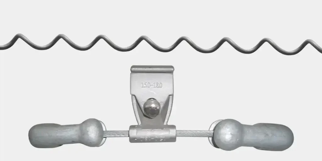
| Model | Clamp Diameter Range (mm) | Total (mm) | Clamp W (mm) | Weight (kg) |
| 4D-30 27.0 | 27.0-22.3 | 383 | 52 | 2.5 |
| 4D-30-23.4 | 23.4-19.5 | |||
| 4D-30-20.3 | 20.3-16.5 | |||
| 4D-30-8.0 | 18.0-15.0 | |||
| 40-30-16.0 | 16.0-14.0 | |||
| 4D-30-14.0 | 14.0-12.0 | |||
| 4D-20-27.0 | 27.0-22.3 | 330 | 1.4 | |
| 4D-20-23.4 | 23. 4-19. 5 | |||
| 4D-20-20.3 | 20.3-16.5 | |||
| 4D-20-18.0 | 18.0-15.0 | |||
| 4D-20-16.0 | 16. 0-14.0 | |||
| 4D-20-14.0 | 14.0-12.2 |
Collocation
Normally used for the anti-shaking facilities of OPGW optical cables, and also ADSS Optical cables.
Configurations for the Installation Quatitier of OPGW Anti-shaking Hammers
| Clable Diameter (mm) | Span (m) | |||
| d<12 | 100 〜300 | 300 〜600 | 600 〜900 | |
| 124dV22 | 100 〜350 | 350 〜700 | 700-1000 | 1000- 1200 |
| Numbers of Vibration Damper | 2 | 4 | 6 | |
Configurations for the Installation Quatitier of ADSS Anti-shaking Hammers
| Clable Diameter (mm) | Span (m) | |||
| d<12 | 100 〜250 | 250 〜450 | 450 〜700 | |
| 12<d<22 | 100~250 | 250-500 | 500 〜800 | 800-1000 |
| Numbers of Vibration Damper | 1 | 2 | 4 | 6 |
Choose Model
Two factors shall be included in the sizing; one is the selection of hammer head; the other is diameter of installation. In total, selection of anti-vibration hammer should include the key technical parameter of OPGW cables, like tension, wind speed and landform, etc.
Selection of Weights
Theortical foumular: Z= (T*m) 1/2
Annotation: Z means the characterizeid impedance value of optical cable, which shall define type of anti-vibration facility
If Z>110, then 4D-30 shall be chosen;
If Z<=110, 4D-20 shall be utilized
Note:
T means 18%-25% of rated anti-pulling intension of optical cable (unit:KN);
M means the unit weight of cable (kg/km).
Selection of Clipping Diameter
Clipping diameter means the optical cable diameter plus twice the diameter of internal teist thread of anti-strain clamp (or overhanging clam). For example, in the installation of protection lines, clipping diameter shall eaqual to the diameter of optical cable plus twice diameter of protection lines.
Localization of Installation
Install per the anti-vibration scheme.
Note:
1、According to the calculation, if the calculated installation position of anti-vibration hammer falls onto the internal twisted thread, the installation can proceed with no protection lines installed.
2 、 If the calculated installation position of anti-vibration hammer falls onto the optical cable, then the protection lines should be installed, and attention should be paid to keep the end of protection lines should at least 50mm from the end of internal twisted thread.
3 . If the calculated installation position of anti-vibration hammer falls onto the external twisted thread, then it can be installed directly onto the internal twisted thread with tiny excursion allowed, but center of anti- vibration hammer should be more than 50mm from the end of external twisted thread.
4 .Direction of the hammer head: Towards the iron tower.
Armor Rod
| Model | Cable Diameter (mm) | Materical | Length (mm) | Weight (kg) | Model | Cable Diameter (mm) | Materical | Length (mm) | Weight (kg) | ||
| TF0800 | 7.4-8.0 | Anti-rust Aluminum Alloy | 400 | 0.12 | TF1410 | 13.7-14.1 | Anti-rust Aluminum Alloy | 500 | 0.23 | ||
| TF0880 | 8.1-8.8 | 400 | 0.12 | TF1430 | 14.2-14.3 | 0.23 | |||||
| TF0960 | 9.0-9.6 | 450 | 0.15 | TF1450 | 14.4-14.5 | 0.23 | |||||
| TF1010 | 9. 7-10.1 | 450 | 0.15 | TF1510 | 14.6-15.1 | 0.25 | |||||
| TF1060 | 10.2-10.6 | 450 | 0.17 | TF1580 | 15.2-15.8 | 0.28 | |||||
| TF1110 | 10.7-11.1 | 450 | 0.17 | TF1600 | 15.9-16.0 | 550 | 0.30 | ||||
| TF1160 | 11.2-11.6 | 500 | 0.19 | TF1690 | 16.1-16.9 | 0. 30 | |||||
| TF1170 | 11.7-11.7 | 500 | 0.21 | TF1730 | 17.0-17.3 | 0. 30 | |||||
| TF1200 | 11.8-12.0 | 500 | 0.21 | TF1800 | 17.4-18.0 | 0. 33 | |||||
| TF1270 | 12.1-12.7 | 500 | 0.21 | TF1840 | 18.1-18.4 | 0.33 | |||||
| TF1290 | 12.8-12.9 | 500 | 0.23 | TF1880 | 18.5-18.8 | 0. 35 | |||||
| TF1360 | 13.0-13.6 | 500 | 0.23 | ||||||||
